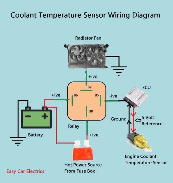
[DIAGRAM] 2 Wire Temp Sensor Coolant Temperature Sensor Wiring Diagram
The wiring diagram for the coolant temperature gauge typically includes three main components: the temperature sensor, the gauge, and the power source. The temperature sensor is connected to the engine block, while the gauge is connected to the dashboard.
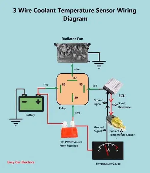
3 wire coolant temperature sensor wiring diagram AsmaaAkasha
5.3 coolant temp sensor wiring. I swapped a 5.3 with s turbo into my 67 Chevelle. Reworked the stock harness and removed the unnecessary circuits like evap, AC, transmission controls (have a th400 in it) etc. I followed the steps from LT1swap.com which was very helpful.
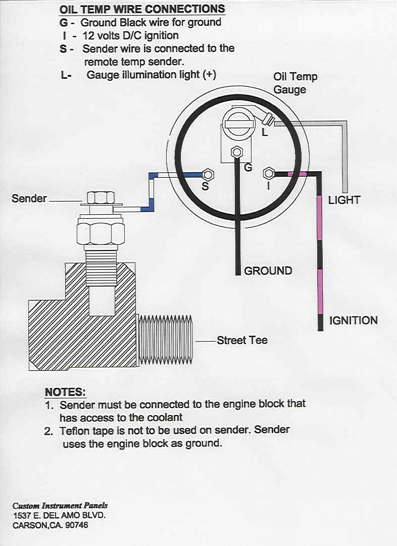
Installing oil temperature gauge out of Ram SRT10 Dodge SRT Forum
On todays video I will be showing you how I got my factory temp sensor gauge working in my square body Chevy ls swap project truck using a 3 wire factory LS coolant temp sensor..

Coolant Temperature Sensor Wiring Diagram Hanenhuusholli
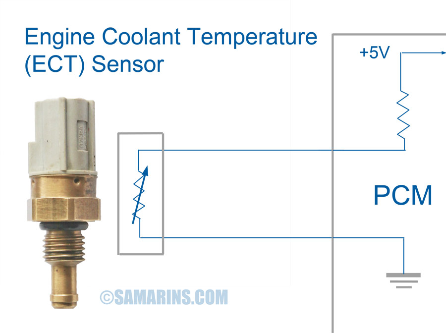
In its most basic form, the coolant temperature sensor has three wires - one that is connected to the battery positive terminal, one that is connected to the ground wire and one that is connected to the engine block or cylinder head. The resistance of the coolant temperature sensor varies as the temperature of the engine coolant changes.

Coolant Temperature Sensor Wiring Diagram Free Wiring Diagram
OEM 2gr coolant sensor has two wires, color may differ depending on your harness or wiring so its easier to look at pin positions. Pin one from the two pin connector goes to pin 1 of the three pin connector. Pin two from the two pin connector goes to pin 2 of the three pin connector. Single OEM gauge wire goes to pin 3 for the three pin connector.

Engine Coolant Temperature Sensor Wiring Diagram Wiring Diagram
27 I bought the 3 wire ECT (88988301) but all 3 wires are the same color and it did not come with a diagram. Which wires go to the ECM (1 yellow and 1 gray on my 6.0L engine harness) and which wire goes to my temp gauge (green wire for my 93 Yukon)??
3 wire coolant temperature sensor wiring diagram NazaninSharifah
0:00 / 12:11 EASIEST WAY!!! HOW TO RUN GAUGE ON LS SWAP WITH 3 WIRE COOLANT TEMP SENDER!!! Blaser Builds 62.6K subscribers Subscribe Subscribed 86K views 6 years ago In this video I show.
Coolant Temp Sensor Reading Low Catalog Library
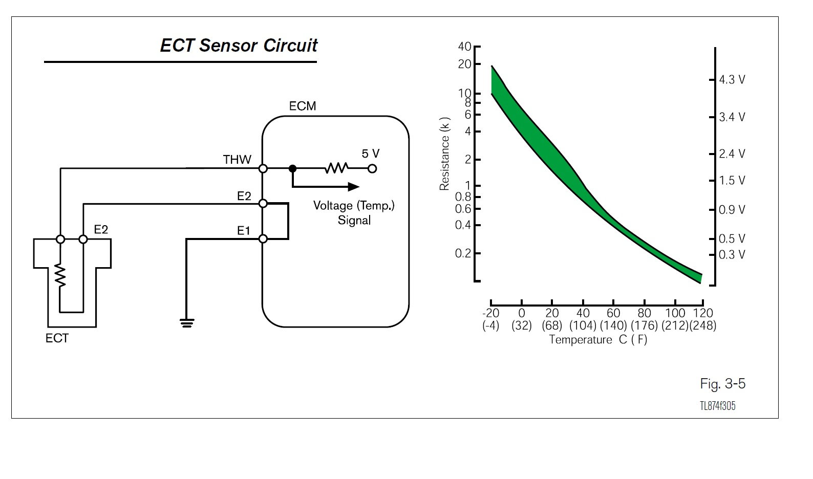
ECT Sensor & Wiring DiagramAmazon Printed Bookshttps://www.createspace.com/3623928Amazon Kindle Editionhttp://www.amazon.com/Automotive-Electronic-Diagnostic.

Understanding Coolant Temperature Sensor Wiring Diagrams Wiring Diagram
A second coolant temperature sensor could be installed in another part of the engine, or in the radiator.. (typically 5 Volt); another wire is the sensor ground. Both the reference voltage and the ground must be checked first.. it means that the ECT sensor circuit was open at the time of the fault. It could be a problem with the sensor.
1, 2 & 3 Wire Coolant Temperature Sensor Wiring Diagram
•The coolant level sensor is a switch, and is used to measure the level of the engine coolant in the radiator top tank. Yes: Go to Step 3 No: Repair wiring and retest Key ON, Coolant Probe UNPLUGGED, Coolant Module PLUGGED IN 3Connector 6401 (A to Gnd) < 0.25v. (Terminal A is the (+) and wire K34 should be wired to it, Terminal B is the.

[DIAGRAM] Impala Coolant Level Wiring Diagram
Here is a basic wiring diagram for a 3-wire coolant temperature sensor: Reference Voltage ----- ECU | Signal Wire ------ ECU | |-------- Ground Tips for Proper Wiring Always refer to the vehicle's service manual or reliable sources for the specific wiring diagram related to your vehicle's make, model, and coolant temperature sensor type.
car temperature gauge wiring diagram
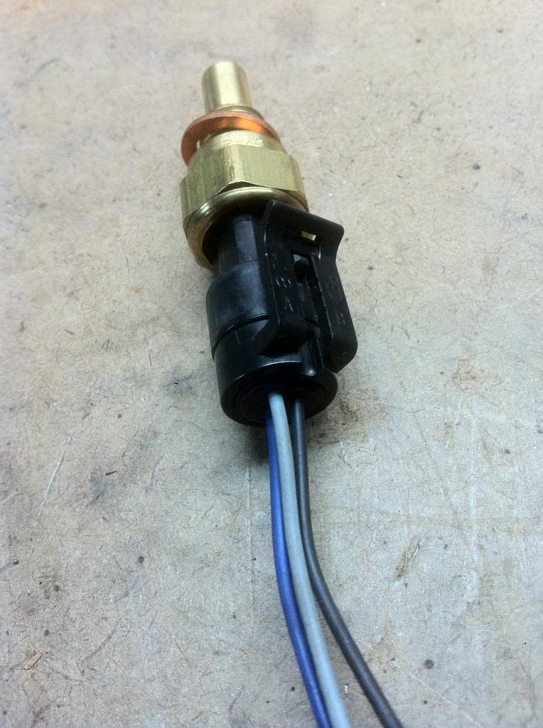
You're confusing the temperature sender (one wire and a grounded body) and the ECT sensor (two wires, not grounded to the block). The sender operates the gauge in the instrument cluster. The sensor sends info to the ECU. He's not having monumental problems here. Just needs to replace the pigtail on the wiring harness.
Engine Coolant Temperature Sensor Circuit Diagram General Wiring Diagram
Most 5V temperature sensors are 3-wire. The 5V temperature sensor's 5V & Ground wires don't consume any I/O, only the Pin Mapped signal wire does. Does your EFI main harness have the Power Tap connector as shown in the center of this diagram?
25 Ls1 Coolant Temp Sensor Wiring Diagram Wiring Database 2020
A coolant temperature sensor wiring diagram is essential for understanding how a car's engine cooling system works. It can help you troubleshoot issues with the cooling system and avoid costly repairs. The ECT sensor comes in different wiring diagrams and colors depending on the car.

Where Is A Coolant Temperature Sensor Located
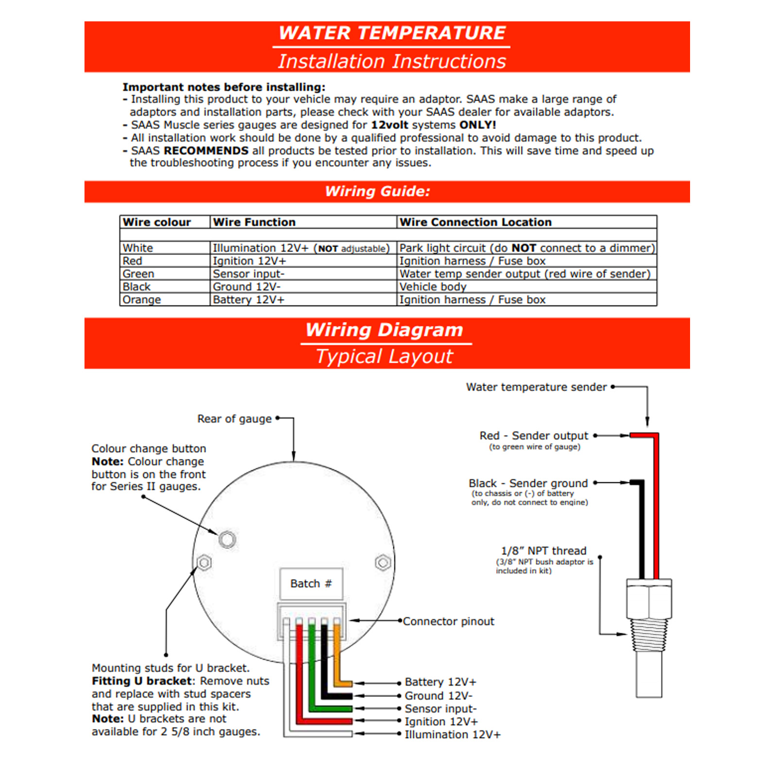
Wiring up coolant temp gauge-Confusing wiring diagram. Hi everyone. I installed an aftermarket coolant temp gauge. the wiring is actually pretty simple. 3 wires for the gauge. signal. The diagram included in the kit just says ground for ground wire. I pulled 12v from the ignition switch. signal wire comes straight from the sensor.
.jpg)
Inside a Car Coolant Temperature Sensors
The testing steps of the ECT goes as follows: Disconnecting the ECT sensor from the electrical connector. Measure the temperature of the surface of the engine using either a cooking thermometer or an infrared thermometer. Note the temperature reading of the surface of the engine. Set the Digital Multimeter to the resistance settings.
