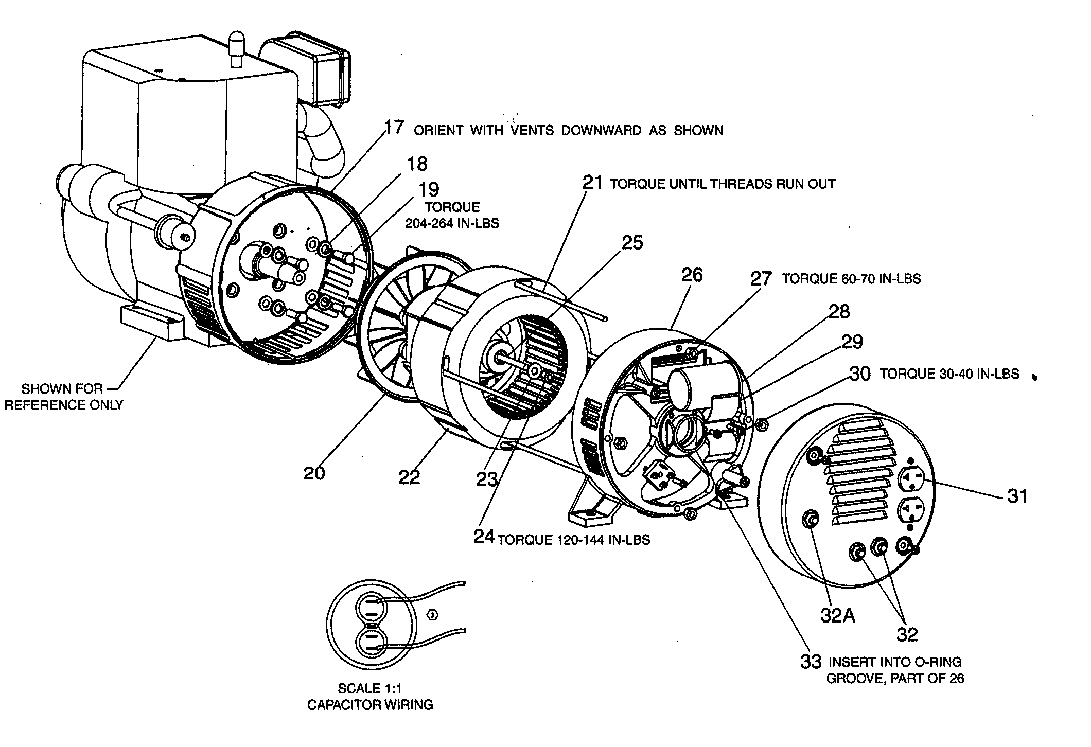
Homelite HG3500 Series Electric Generator Parts Diagram for General
Electric generator diagram. Fig. 2: A diagram to show how an electric generator is used to help convert wind power into useful electric power for the national grid. The diagram above shows how an electric generator can help us generate electricity using a wind turbine. Firstly, the turbine is forced to spin by the wind.
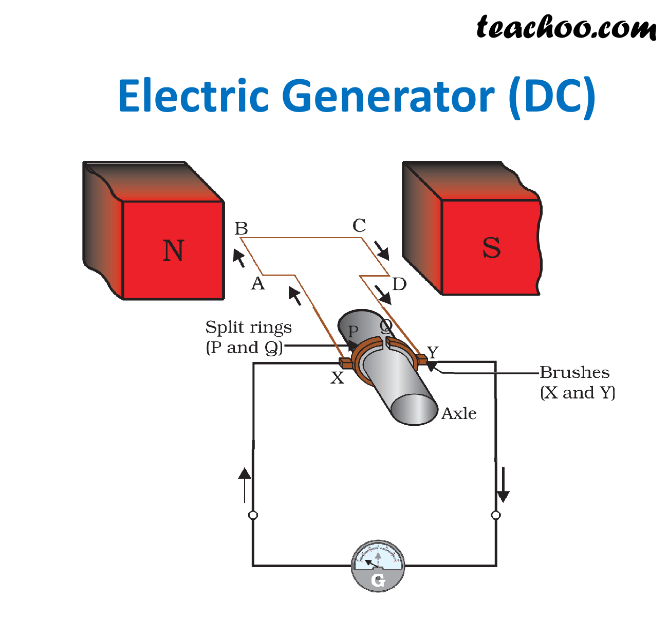
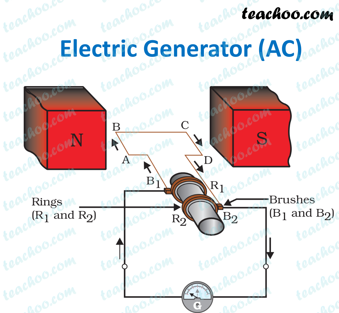
Electric Generator Class 10 Working, Principle, Diagram Teachoo
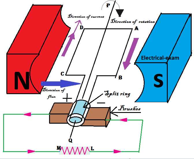
An electric generator works by converting mechanical energy into electrical energy. It operates based on the electromagnetic induction principle, which is the creation of an electric current by moving a wire next to a magnet.
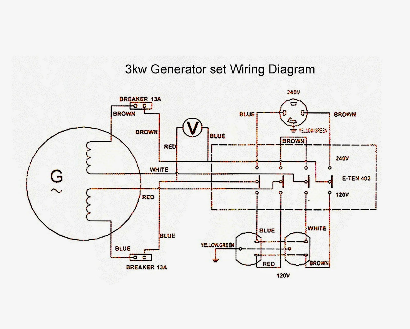
July 2014 Electrical Winding wiring Diagrams
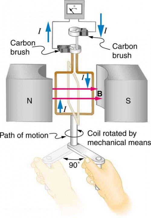
Cars use a type of ac generator called an alternator close alternator An electrical generator which produces alternating current,. The diagram shows four different positions of the coil in an.
Electric Generator Class 10 Easy Diagram Diagram Media
Electric generator schematic diagrams are essential for understanding the structure and functioning of electric generators. These diagrams depict the different components and connections of the generator, providing a visual representation of how electricity is generated. By understanding these diagrams, individuals can troubleshoot and repair.

Electric Generator Diagram Design ElectricalEngineering EEE
Electric Generator is a device that converts mechanical energy into electrical energy. The electricity being produced at various power stations is coming from the electric generator installed there.
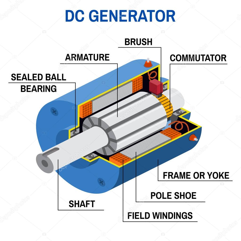
Dc generator cross diagram. — Stock Vector ©
The Electromechanical process of Electric Generator Diagram is shown schematically in Fig. 1.1. Under steady conversion conditions, TPM (prime mover) = TG (generator) and the turbine and generator run at steady speed. Other than lighting and heating, the major use of electric energy is made by converting it back to the mechanical form to run.

Stamford Generator Windings Wiring Diagram Wiring Diagram
What makes electric power possible—and indeed practical—is a superb electromagnetic device called an electricity generator: a kind of electric motor working in reverse that converts ordinary energy into electricity. Let's take a closer look at generators and find out how they work!
Electric Generator Diagram And Working See More...
Electrical generator diagrams are visual representations of the internal components and connections of an electrical generator. They provide a clear and concise overview of how the generator functions and how the different components are connected to generate electricity.
Electric Generators Physics
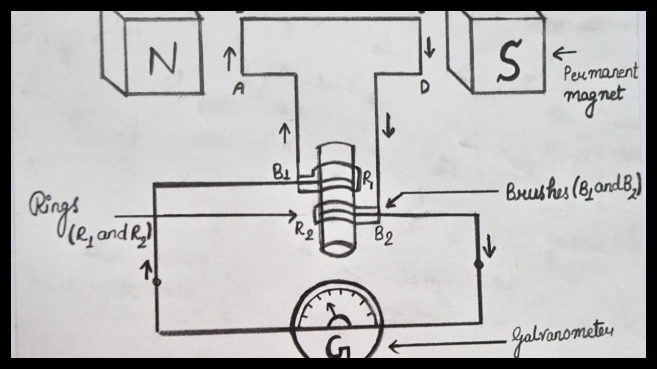
What Is an AC Generator? AC generator is a machine that converts mechanical energy into electrical energy. The AC Generator's input supply is mechanical energy supplied by steam turbines, gas turbines and combustion engines. The output is alternating electrical power in the form of alternating voltage and current.
Electric Generator Class 10 Working, Principle, Diagram Teachoo
In electricity generation, a generator [1] is a device that converts motion-based power ( potential and kinetic energy) or fuel-based power ( chemical energy) into electric power for use in an external circuit.
kubota generator wiring diagram Wiring Diagram
This training module has been developed to provide you with information pertaining to devices known as Basic AC Electric Generators. The information in this training module is designed to increase your knowledge and improve your abilities as they relate to the module.

Electric Generator Schematic Diagram
Circuit Diagram is a free application for making electronic circuit diagrams and exporting them as images. Design circuits online in your browser or using the desktop application.
electric generators diagram
direct current. This type of generator is called D.C. generator. Similarly, instead of a half ring, if a full ring is used then, A.C. current can be generated and such a generator is called an A.C. generator.

☑ Induction Ac Generator
Main Electrical Components: Diagram Circuit: Generator with a PMG As the PMG rotor rotates, it produces AC voltage in the PMG stator. The regulator rectifies this voltage and applies DC to the exciter stator. A three-phase AC voltage appears at the exciter rotor and is in turn rectified by the rotating rectifiers.
Electric Generator Class 10 Working, Principle, Diagram Teachoo
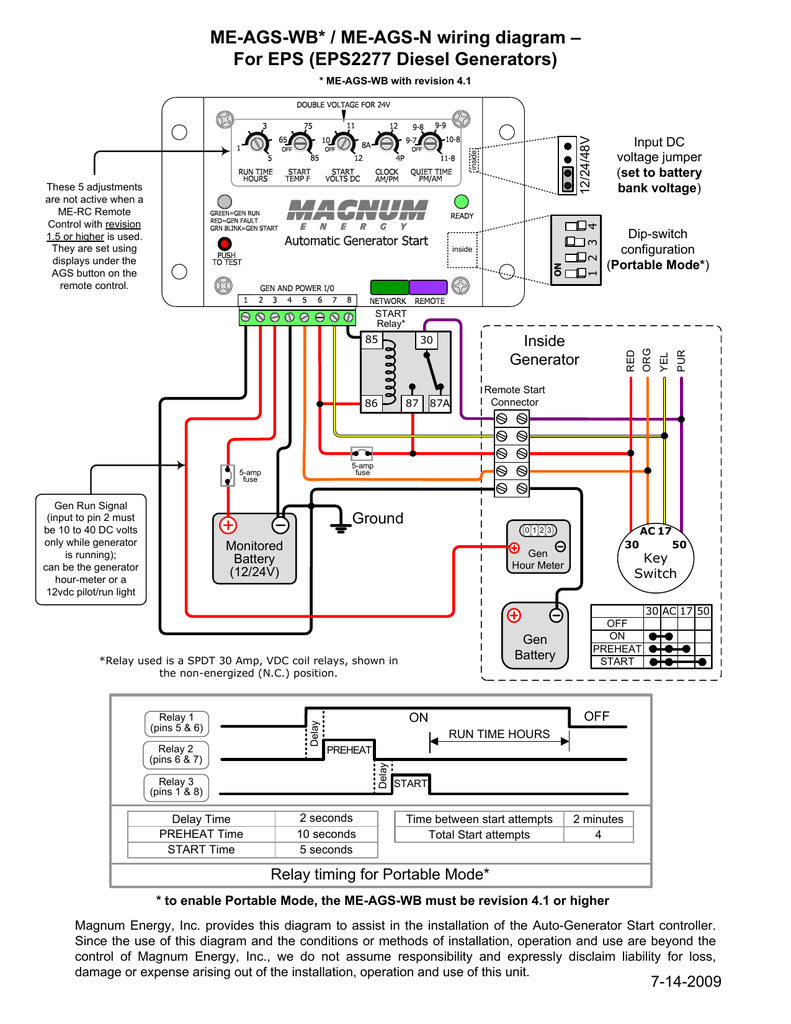
DCA45SSIU2 Generator and Engine Wiring Diagram. DCA45SSIU3 Generator and Engine Wiring Diagram. DCA45USI ECU Wiring Diagram. DCA45USI ECU-EGS Engine Wiring Diagram. DCA45USI W/ EGS/Key Engine Wiring Diagram. DCA60SSAI Generator and Engine Wiring Diagram. DCA60SSI2 Generator and Engine Wiring Diagram. DCA70SSIU Generator and Engine Wiring Diagram.

Electric Generator Diagram EEE Electronics Electrical Components
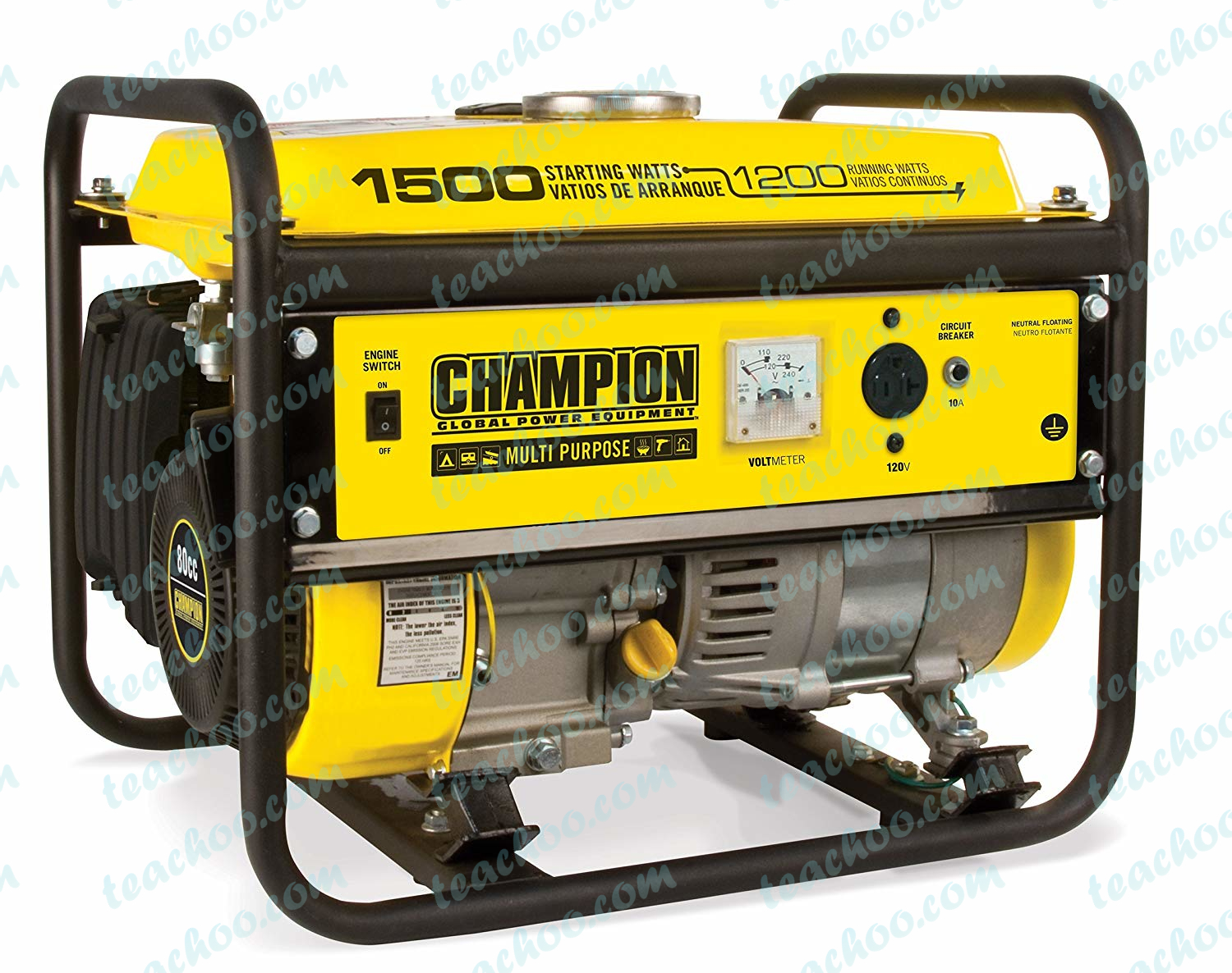
A schematic diagram of the construction of a generator (Reference: bigrentz.com) Each part of the generator in detail 10 Parts of the Generator are: Engine Fuel System Voltage Regulator Alternator Cooling System Exhaust System Lubrication System battery Control Panel Main Assembly Frame
